Product
Part Number:
Part Number:
Product
Description:
Tech
Sheet
Number:
Number:
054-5345-001
AS1X-HP
Mechanical Set Retrievable Production Packer,9-5/8",43.5-53.5#
054-5345-001
Click here for
Product Part Number: |
Product
Description: |
Tech
Sheet Number: |
| 054-5345-001 |
AS1X-HP
Mechanical Set Retrievable Production Packer,9-5/8",43.5-53.5# |
054-5345-001 |
Click here for |
||
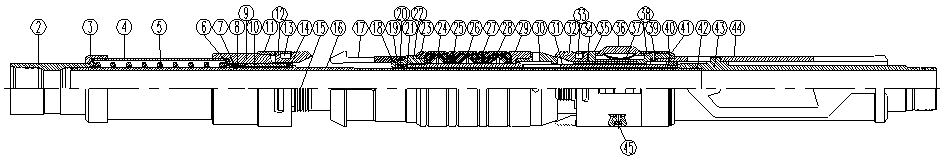
OPERATION INSTRUCTIONS: AS1X
Running:
Run packer to setting depth. Pick-up on the tubing and rotate 1/4 turn to the right at the packer. Lower tubing to engage slips, release right-hand torque while moving tubing downward. (Tubing must be able to rotate back to the left at packer to lock into set position.) Continue to set weight on packer to pack-off elements. After setting weight on packer, pick-up on tubing and pull tension in packer to engage upper slips and complete element pack-off. Repeat setting weight and pulling tension two to three times before landing tubing. Packer may be landed in compression, tension or neutral position.
Retrieving:
The releasing procedures are the same whether the packer has been tension or compression set. Set-down weight (normally 1,000 lbs. is sufficient) on the packer and rotate the tubing 1/4 turn right at the packer, then pick-up holding the right-hand torque. The internal by-pass will open, allowing pressure to equalize. Further pick-up releases the releasing sequential slip system, relaxing the elements, allowing the packer to be removed from the well. The packer can be moved and reset without tripping the pipe if the elastomers have not been permanently altered from the well environment.
PRESSURE AFFECTED AREAS GUIDE
The pressure affected areas guide is a calculation of the end area affect on the packer mandrel based on the tubing size used. This effect should be considered in conjunction with the other factors, which elongate or shrink the tubing.
| PACKER
SIZE (IN.) |
PRODUCT NUMBER |
CASING WEIGHT (LB/FT) |
TOOL ID (IN.) |
TUBING SIZE (IN.) |
PRESSURE ABOVE (IN^2) |
PRESSURE BELOW (IN^2) |
4
1/2" |
054-5340-002 |
9.5-13.5 |
1.938 |
2.375 |
0.120
UP |
1.189
UP |
054-5340-003 |
13.5-15.1 |
1.938 |
2.375 |
0.120
UP |
1.189
UP |
|
5"
|
054-5340-006 |
18.0-20.8 |
1.938 |
2.375 |
0.120
UP |
1.189
UP |
2.875 |
2.177
UP |
0.365
DOWN |
||||
054-5340-007 |
11.5-15.0 |
1.938 |
2.375 |
0.120
UP |
1.189
UP |
|
2.875 |
2.177
UP |
0.365
DOWN |
||||
| 5
1/2" |
054-5341-001 |
20-23 |
1.938 |
2.375 |
0.916
UP |
2.220
UP |
| 2.875 |
1.146
UP |
0.666
UP |
||||
| 054-5341-002 |
13-17 |
2.375 |
0.916
UP |
2.220
UP |
||
| 2.875 |
1.146
UP |
0.666
UP |
||||
| 054-5341-006 |
20-23 |
2.375 |
2.375 |
2.062
DOWN |
3.366
UP |
|
| 2.875 |
0.00
DOWN |
1.812
UP |
||||
| 054-5341-007 |
15.5-17 |
2.875 |
2.062
DOWN |
3.366
UP |
||
| 2.875 |
0.00 DOWN |
1.812 UP |
||||
| 7" |
054-5342-003 |
26-32 |
3.000 |
2.375 |
3.87
DOWN |
5.17
UP |
| 2.875 |
1.80
DOWN |
3.62
UP |
||||
| 3.500 |
1.33
UP |
1.26
UP |
||||
| 054-5342-004 |
17-26 |
2.375 |
3.87
DOWN |
5.17
UP |
||
| 2.875 |
1.80
DOWN |
3.62
UP |
||||
| 3.000 |
1.33
UP |
1.26
UP |
||||
7
5/8" |
054-5343-001 |
33.7-39 |
2.500 |
2.375 |
3.87
DOWN |
5.17
UP |
2.875 |
1.80
DOWN |
3.62
UP |
||||
3.500 |
1.33
UP |
1.26
UP |
||||
9
5/8" |
054-5345-001 |
43.5-53.5 |
4.000 |
2.875 |
11.11
DOWN |
12.92
UP |
3.500 |
7.98
DOWN |
10.57
UP |
||||
4.000 |
5.03
DOWN |
8.11
UP |
||||
4.500 |
1.70
DOWN |
5.30
UP |
|
Setting Force Guide |
|
|
Packer Size (IN.) |
Minimum Force Required Packer (LBS.) |
|
4-1/2 |
10,000
|
|
5
|
10,000
|
|
5-1/2
|
10,000
|
|
7
|
15,000
|
|
7-5/8
|
15,000
|
|
9-5/8 |
25,000 |
|
Required To Pack-Off Packing Elements Systems |
||||
|
Classification
|
Temp.
Range
|
Element Duro |
||
|
End
|
Middle |
End |
||
|
Low Temperature |
60-125 |
80
|
60 |
80 |
|
Standard Tool |
125-225 |
90
|
70 |
90 |
|
Moderate
Temp.
|
225-275
|
90
|
80
|
90
|
|
High
Temperature
|
275-UP
|
Contact
Tech. Sales
|
||
| Specifications |
||||||||||
| Casing |
Setting Range |
Absolute Travel Limits |
Packer |
Packer |
Thread |
|||||
| OD |
WT |
Min ID |
Max ID |
Slips |
Drag
Block |
|
|
|
||
| Min
OD. |
Max OD |
Min
OD. |
Max OD. |
|||||||
|
9 5/8" |
43.5-53.5 |
8.535 |
8.755 |
9.091 |
9.230 |
8.250 |
9.656 |
8.250 |
4.000 |
4 1/2-8 EUE |
NOTES: Lubricate o-ring and o-ring grooves and all mating threads before assembly.